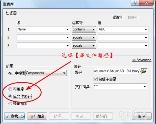
In this section of the tutorial, we will locate the components required, set up their component properties and then wire the schematic. Before we can run a simulation, the schematic must contain components with SIM models attached, voltage sources to power the filter, an excitation source, a ground reference for the simulations and some net labels on the points of the circuit where we wish to view waveforms. Now we can create the Filter circuit shown below. Navigate to a location where you would like to store the schematic on your hard disk, type the name Filter.SchDoc in the File Name field and click on Save. SchDoc extension) by selecting File » Save As.
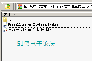
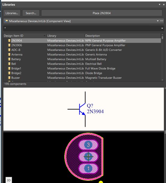
#Altium Miscellaneous Devices Intlib download
If you do not have the time to draw the schematic from scratch, you can download a similar project Filter.PrjPCB from the Download Examples and Reference Designs page. This schematic will be for a Filter circuit.


Next, we will create a new schematic sheet to add to the empty project file. Navigate to a suitable location, type the name Filter.PrjPCB in the File Name field, and click on Save.

The new project file, PCB Project1.PrjPCB, is listed, with no documents added. Select File » New » Project » PCB Project from the menus.To start the tutorial, create a new PCB project: We will start by creating a new project file and then add a blank schematic sheet. This tutorial takes you through the process of creating a simulation-ready schematic, which is then used to run a number of circuit simulation analyses. Setting Up a Transient/Fourier Analysis.Locating Components and Loading Libraries.All capacitors are Murata – because it was easier to scrape one manufacturer without getting thousands of duplicate value parts. They all contain similar parameters as the resistors. There are 4,739 capacitors in 6 different libraries split up according to package size: 0201, 0402, 0603, 0805, 1206, 1210. I scraped the data from Digi-Key to create these libraries and thus they contain a significant number of parameters that you can use for your BOM generation. The resistors are split up into 6 different IntLibs according to package size: 0201, 0402, 0603, 0805, 1206, 2512. There are 6,029 resistors, all are Panasonic ERJ series. Panasonic ERJ resistors libraries download I’ll start here by giving you the libraries I generated and I’ll make another post about how I generated them. The database can take many forms such as an Excel spreadsheet, Microsoft Access database, or in theory any SQL or ODBC source. I wanted to figure out on my own how I could scrape data from Digi-Key and (almost) automatically create part libraries.Īltium Designer has a powerful feature called Database Libraries which take an external database and link entries to a schematic symbol and physical footprint. I realize you can get many of these parts from Altium or other third parties.

I generated several libraries for Altium (or Circuit Studio) using Database Libraries which I then exported to IntLibs.


 0 kommentar(er)
